DESCRIPTION
Airplane
The Model ST-A Airplane is a two-place, low wing monoplane.
Fuselage
The fuselage is of moncoque-type construction employing longerons to reinforce the stressed skin at points of concentrated load - at stick control mountings, seats, floors, cockpit cut-outs and at the tail section. Eight elliptical transverse bulkheads, suitably spaced, are covered with heavy gauge aluminium alloy skin.
(Note: For purpose of reference in this text the bulkheads are referred to by number. Number on (#1) is the front bulkhead at the firewall. The balance are numbered in sequence ending with #8 at the tail.)
Bulkhead #2 and the lower section of bulkhead #3 are of welded chrome-molybdenum steel, S.A.E. 4130X, construction to carry the engine and wing loads.
Engine Compartment and Cowling
A stainless steel firewall isolates the engine compartment from the cockpits. The engine mount is attached to bulkhead #1 at four points and is readily removable without dismounting the engine. Cowling is N.A.C.A. type supported by two rings and four longitudinal members attached to the engine mount. The side panels are attached to the support frame with Dzus fastners.
Wings
The wings are constructed in four fabric covered sections - two stub wings and two outer panels. The outer panels are wire braced N.A.C.A. airfoil, constructed of spruce spars, welded steel tube compression struts and aluminium alloy ribs. The stub wings are of welded steel tube construction, incorporating a walkway.
Ailerons and Flaps
The ailerons and flaps are constructed of steel tube spars and aluminium alloy ribs, fabric covered. The noses are covered with aluminium alloy sheet carried well back of the spars to form a perfect contour.
Tail Surfaces
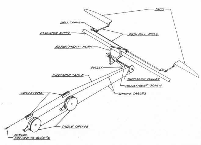
All tail surfaces are constructed of aluminum alloy tube spars, to which are riveted the aluminum alloy ribs. All are fabric covered. The elevators incorporate metal trimming tabs for longitudinal balance.
Landing Gear and Tail Wheel
The landing gear is treadle type welded steel tube construction with shock absorber strut of oleo-spring type. Each leg consists of four component parts - (1) Vee strut assembly, (2) upper fork and shock strut assembly, (3) treadle fork assembly, and (4) wheel and brake assembly. The Vee strut, wheel fork and axle are heat treated to an ultimate tensile strength of 180, 000 pounds per square inch. Wheels are equipped with Goodyear internal disc type brakes.
The tail wheel is a steerable and full swiveling unit of welded steel tube construction, equipped with oleo shock strut.
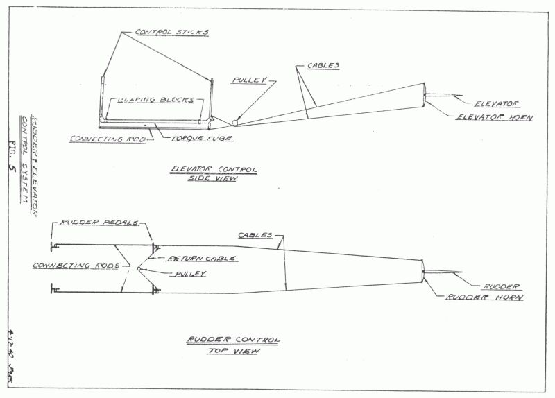
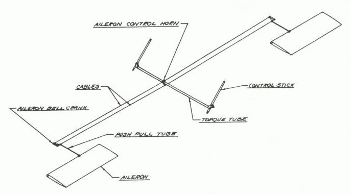
Flight Controls
Surface controls are operated through cables by conventional type control sticks, rudder pedals, self-locking flap handle, tab cable drum and toe (s/b heel) brakes mounted on rudder pedal.
Engine and Propeller
ST-A airplanes are equipped with Menasco 125 h.p. type C4 engines. Propeller is Sensenich 80R-1 wood type.
Fuel and Oil Tanks
Fuel is carried in one 24 gallon aluminium tank mounted between the firewall and front cockpit. Oil is carried in a two gallon aluminum tank mounted on the engine mount frame.
Pilot's Seats
Pilot's seats are of aluminum alloy consstruction with bottom well for cushion or parachute. Seats are fully adjustable by hand operated worm gear mechanisum.
Safety Belts
Safety belts are provided and are attachable to brackets mounted on the floor supports.
Fire Extinguisher
A fire extinguisher is mounted between cockpits.
Utility Bag
A leather bound canvas utility bag is attached to the back of the front seat and is accesible from either cockpit.
Bulkhead Dresser
A leather reinforced canvas dresser, attached to bulkhead #4 by "Lift the Dot" fasteners closes off the tail section of the fuselage from the rear cockpit.
Windshields
Windshields are of Plexiglass formed to contour of fuselage and mounted in a frame of aluminum alloy.
Instruments
Standard equipment for dual control consists of two each of the following instruments: altimeter, tachometer, compass, air speed indicator, oil temperate gauge, fuel pressure gauge, and oil pressure gauge.
SPECIFICATIONS
Airplane General
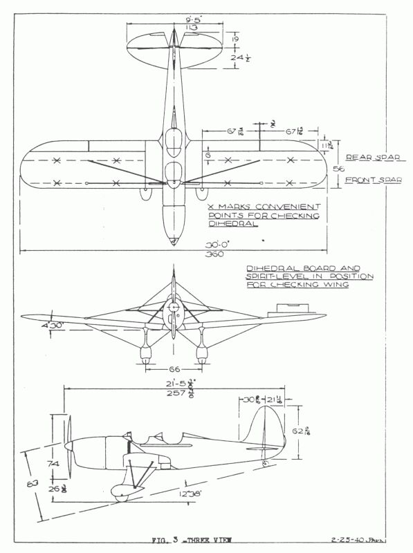
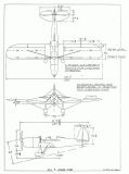
Overall Span 30 Ft. 0 In.
Overall Length 21 Ft. 5-3/8 In.
Overall Height, Thrust Line Level at Fin 9 Ft. 1-3/4 In.
Overall Height, At Rest (At Engine Cowl) 6 Ft. 11-1/2 In.
Height, Propeller Hub, Thrust Line Level 5 Ft. 3-3/8 In.
Height, Propeller Hub, at Rest 6 Ft. 3 In.
Clearance, Propeller Tips, Thrust Line Level 1 Ft. 11 In.
Wing
Total Area (Including Aileron and Flaps) 124 Sq.Ft.
Chord 56 In
Incidence 3 Deg 0 min
Dihedral 4 Deg 30 min
Sweepback 0 Deg
Area of Other Surfaces
Aileron 5.693 Sq.Ft.
Flap 6.270 Sq.Ft.
Stabilizer 12.000 Sq.Ft.
Elevator 10.000 Sq.Ft.
Tab 0.314 Sq.Ft.
Fin 4.700 Sq.Ft.
Rudder 7.250 Sq.Ft.
Weights
Weight Empty 1101 Lbs.
Useful Load
Crew, two at 170 340 Lbs.
Fuel, 24 Gal. 144 Lbs.
Oil, 2 Gal. 15 Lbs.
Gross Weight 1600 Lbs.
Wing Loading 12.7 Lbs/Sq.Ft.
Power Loading 12.8 Lbs/H.P.
Engine
Bore 4.75
Stroke 4.125
Compression ratio 5.5 to 1
*Fuel Consumption
Cruising 7-3/4 Gal.per hr.
Full Throttle (2175 R.P.M.) 10-1/2 Gal.per hr.
Fuel Capacity 24 Gal.
*Oil Consumption (Normal) 1.5 pts. per hr.
Oil Capacity 2 Gal.
Note: Fuel and Oil consumption quoted by Engine Manufacturer.
OPERATION
This section of the Manual outlines in brief form approved methods for the safe handling of the airplane on the ground and in the air. Engine and flight controls are, with minor exception, conventional in design and operation. A few departures from conventional design are incorporated in the Ryan ST-A which improve the performance of the airplane and add to the convenience of the operator. These unusual features are pointed out in this section of the Manual. Special instructions are also given with respect to certain restrictions and prohibitions whcih should be observed while operating the airplane.
Ground Handling
Three men are required for safe handling of the airplane on the ground; one man at each wing tip, and one at rear of airplane. Hand holds are provided at rear of each wing tip. Do not take hold of wing tip bow, ailerons, or flaps. The man at the rear of the airplane should take hold of the upper brace wire fitting attached to fin spar. If hold is taken on rudder be sure to graps at one of the ribs. Do not raise tail wheel from ground. Jack pads are located at bottom of landing gear brace tube.
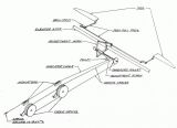
Hoisting
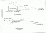
The turn-over post will carry the weight of this airplane empty. It is located about four inches ahead of the center of gravity. Make a special hoisting cable with fittings as shown in Fig. 4. Remove 3/16" bolts which hold turn over post cap. Bolt special hoist fitting to turn-over post. Clamp attaching fitting to #4 bulkhead. Gas and oil tanks should be drained before hoisting in order to retain the normal center of gravity.
Towing
Towing lugs are located on inner side of each landing gear strut fork just rear of wheels. For towing backwards use special dolly under tail wheel. A tail wheel saddle should be swivel-mounted on bed of this dolly. Load tail before towing.
Mooring
Mooring lugs are located on under side of front wing spars. Tie down tail wheel and set parking brakes.
Starting the Engine
Turn fuel cock shut off handle to reserve position.
(Note: Engine should be allowed to run, taking fuel from reserve line until take off is made and a safe altitude reached. The shut-off valve may then be turned to use fuel from the main line. When landing turn valve to reserve position dial.)
Retard spark.
Set mixture control to full rich position.
If engine is cold, turn propeller over three to four revolutions with ignition switch "OFF".
Pump throttle two to six strokes depending on the weather conditions. If engine is warm no pumping of throttle is required.
turn magneto swith to "BOTH ON" position.
Open throttle 1/8 or less and turn crank handle slowly simulating hand pull through of propeller. Do not spin.
(Note: Failure of engine to start is frequently due to overpriming. If overpriming is suspected, turn ignition swith to "OFF" position, open throttle wide and turn engine over at least six revolutions. Then return throttle to 1/4 open position and continue normal starting procedure.)
Warm up engine before take off at 600-800 r.p.m. with retarted spark. Recommend oil temperature of 160 deg F.; maximum permissible 200 deg F.
Stopping the Engine
Close throttle after engine dies cut switch.
Then fuel shut off handle to "BOTH OFF" position.
Wobble Pump Operation
This wobble pump is located on the left lower side of the engine mount and is remote controled by a pumping level located on the left side of pilot's seat near the floor. In the event of failure of the engine driven fuel pump, ample fuel may be pumped to the carburetor by operation this handle. Two pounds pressure should be maintained on the fuel pressure gauge.
Operation of Flight Controls
Controls - General - Longitudinal, lateral and directional control in flight is accomplished in a conventional manner.
Elevators - A back pressure on the control stick increases the longitudinal angle of the airplane when in flight, while a forward pressure has the opposite effect and raises the tail, reducing longitudinal angle.
Aileron - Aileron surfaces producing lateral control in flight are actuated by a side movement of the control stick. Movement of the stick to the left (seated in the cockpit) results in depression of the left wing. Movement in the opposite direction has the effect of depressing the right wing.
Rudder Pedals - Foot controlled rudder pedlas are used in maintaining directional control both on the ground and in the air. In both cases, pressure on a rudder pedal produces a yawing turn toward the side on which pressure is applied.
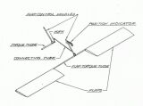
Trimming Tab - Longitudinal balance of the aircraft in flight is controlled by elevator trimming tabs which are actuated by a cable wound drum, left side of cockpits. Cranking the drum forward produces a "nose down" condition. The opposite, or a "nose up" condition is created by cranking the drum backward. This control is rather sensitive, most unbalanced conditions being corrected by less than one turn of the drum.
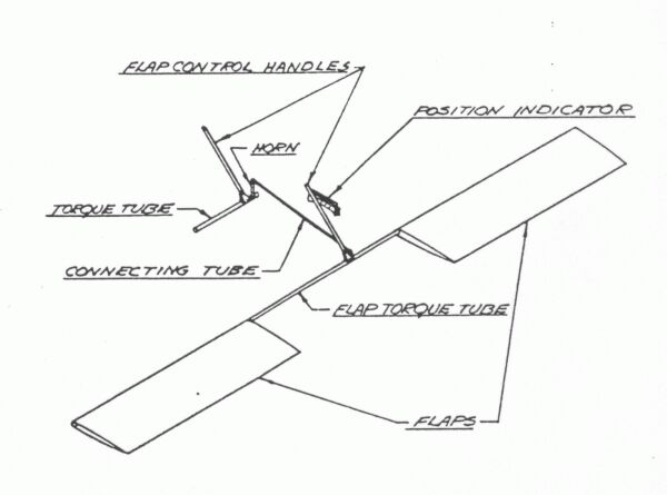
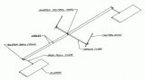
Flaps - Flaps are actuated by the self-locking hand levers located on right side of cokpits. They are used during an approach glide to land and are left extended for duration of the landing roll. Their purpose is to create additional lift and drag, permitting an unusually high angle of descent during glides without building up excessive air speeds. Additional lift afforded gby the extended flaps causes a reduction in landing speed. Flaps can be extended or retratcted at will during flight without creating unusual or dangerous changes in flight characteristics. The flaps can be locked in any one of four extended positions. The degree of flap used determines the amount of drag and lift being created. A setting of from 1/2 to full extended position is advised for normal conditions. These flaps are of no especial benefit in assisting take-offs, therefore are used during approaches and landings only.
Special Instructions
Maneuvers Prohibited
Inverted flight.
Inverted spins.
Outside loops.
Snap rolls at more than 105 m.p.h., indicated.
Slow rolls at more than 120 m.p.h., indicated.
Spins of more than three turns.
Other Restrictions
Do not exceed indicated air speed of 198 m.p.h.
Do not exceed an engine speed of 2175 r.p.m.
Do not exceed fuel pump pressure of 3 pounds.
Do not set parking brake while airplane is in air.
Do not operate engine at full throttle on ground.
INSPECTION
We recommend that owners of Ryan ST-A airplanes adopt a routine schedule of periodic inspection, conforming to regulations of the Civil Aeronautics Authority. Common regard for safety dictates an inspection of all control systems, landing gear, instruments, brace wires, cowling and other parts open to visual inspection, immediatly prior to and not more than seven days preceding flight. There should be a line inspection for each 25 hours of lying time, a more compreshensive inspection for each 50 hours of flying time, and a thorough cleaning and inspection for each 100 hours of lying time.
Civil Air Regulations require that a licensedd airplane shall be given a line inspection by a licensed airman at least once within seven days preceding flight, except, however that there shall be at least one inspection for each 25 hours of flying time. After each 100 hours of flight the aircraft must be given a "periodic inspection" by a licensed mechanic. The results of these inspections shall be entered in the log by the person making the inspection.
For the conveninece of Ryan owners we have prepared inspection schedules which, if followed, will assure safe flying and prevent undue wear and expense.
LINE OR 25 HOUR INSPECTION
Flight Controls
Check for freedom of operation (binding, looseness, interference)
See that cockpits are free of obstructions to controls.
Inspect rudder pedals and equalize cable for tension.
See that control sticks are secure in sockets.
Check control wires and pulleys open to inspection.
Oil hinges on control surfaces.
Engine Controls
Check rods for freedom of movement, lost motion, bent rods.
Check ignition switch connections.
Clean and lubricate ball and socket joints.
Check instruments for pointer accuracy.
Fuel System
Inspect tank and lines for leaks, cracks and breaks.
Check fuel cock for binding.
Clean strainers in tank and carburetor.
Test operation of wobble pump.
Oil System
Inspect tank and lines for leaks, cracks and breaks.
Check condition of hose connections.
Inspect oil drain "Y" for safetying.
Brace Wires
Check condition and finish of brace wires and fittings.
Check wires for tension.
Landing and Tail Gear
Check oleo strut for leaks and loss of pressure.
Check wheels for alignment.
Check swiveling action of tail wheel.
Inspect fairings for security of attachment.
Check air pressure of tires.
Inspect brakes and brake control system - Adjust if necessary.
Engine Cowling
Check condition and security of attachment.
Seats and Safety Belts
Check attachment and fittings.
See that belt catches operate freely.
Check belts for fraying.
Windshields
Check for cracks and distortion.
Check for secuirty of attachment.
Clean.
Propeller
Check general condition and attachment.
Check for tracking and clearance.
50 HOUR INSPECTION
Repeat 25 Hour Schedule and Inspect:
Fuel and Oil Tanks
Drain and clean strainers.
Check secuirty of mounting and condition of straps and padding.
Check and adjust tension of straps.
Check for leaks and anchorage of lines leading from tanks.
Wings and Surfaces
Inspect covers for blisters, torn or loose fabric.
Feel for broken or loose ribs.
Check attachment fittings.
Landing and Tail Gear
Check attachemtn fittings for cracks and elongated holes and worn bolts.
Inspect wheels for excessive side play and worn spacers.
Remove, clean and repack roller bearings.
Brakes
Inspect brake discs for wear.
Inspect brake cables, bellcranks, pulleys.
Fuselage
Check all accessible parts of interior and exterior for cracks, bends, or breaks in structural members, particularly at welds and sharp bends.
Check skin for scratches and dents.
Look for loose bolts, nuts, rivets, etc.
Power Plant Installation
Check engine mount and attachemnt fittings for cracks, breaks, and corrosion.
Check fittings for security of attachment.
Check rubber vibration absorbers for wear.
Check security of mounting of carburetor and other engine accessories.
100 HOUR INSPECTION AND CLEANING
Disassemble and Clean
Complete instructions for removing and disassembling the major assemblies of the airplane are given in the next section of this manual. Clean all parts prior to inspection. Drain holes are provided in cockpits, forward of bulkhead #2, #3, and #4. Clean cockpit and floors with good solvent. Access to rear section of fuselage is available by removing the canvas dresser attached to bulkhead #4. Doped fabric surfaces may be cleaned using lue warm or cold water and mild soap flakes. Rinse with clear fresh water and dry with chamois. Polish outer skin with good non-abrasive metal polish.
Inspection
Repeat more thoroughly and in more detail the 50 hour schedule of inspection.
Inspect all welds for cracks and breaks.
Wings and surfaces
Inspect frame structures.
Check internal brace wires of outer wing panel for tautness.
Check attachemnt of ribs and fittings.
Fuselage and Cowling
Repairs to metal skin, if any should be made with materials of the same specifications and thickness as used in the original structure. Use same spacing of rivets.
Landing and Tail Gear
All cadmium plated tubes and plates should be refinished as conditions require. The Vee strut, the treadle fork and the axle are heat treated to an ultimate tensile strength of 180,000 pounds per square inch. Cracks of up to one inch (1") may be arc welded without requring re-heat treating. Acetylene welding should be followed by heat treating. The steering horn and the fork of the tail wheel are heat treated to 150,000 pounds per square inch.
Engine and Controls
Instructions for overhaul and maintenance of engine are given in the Menasco Handbook furnished with this airplane. Check rubber mountings. Replace if worn. Clean and lubricate ball-socket joints. Check push-pull rods.
Fuel and Oil Tanks
Clean as per instructions given in the "Maintenace and Repair" section of this manual. Check tanks for leaks.
Control Cables
Check for fraying and corrosion.
To prevent corrosion apply mixture of three parts hot tallow and one part white lead.
Fire Extinguisher
Clean, check pump action and refill after each use, or once each twelve month, if not used.
Tires
Remove tires, check casings and tubes.