This webpage is not "official" data and should not be mistaken for nor used as approved data. This document should not be used for the operation or maintenance of a real aircraft.
Elevator and Rudder Control
The elevator control cables were 1/8 inch extra flexible cable which ran from the rear stick socket through the fuselage to a horn on the surface. The forward stick was linked to the rear stick by a control rod. Turn buckles located in the vicinity of the horn provided for adjustment.
The rudder control cables were 1/8 inch extra flexible aircraft cable which ran from each of the rear rudder pedails to a horn on either side of the rudder surface. An equalizer cable (also known as a return cable) ruan from the right rear pedal to the left rear pedal via a pulley which was mounted on the #2 bulkhead. The front pedals were connected to the rear cables with pushrods.
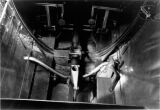
Cockpit Floor |
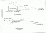
Cockpit Floor |
Elevator Tab Control
The elevator tab could be operated from either cockpit by turning a crank which actuated a continuous cable that ran along the left side of the fuselage. One end of the cable loop passed around a cable that was attached to the rear face of bulkhead #2 while the other end passed around a bronze pulley in the aft fuselage. The bronze pulley was threaded and it's turning actuated a threaded shaft that was mounted on lugs which were welded to the front side of the stabilizer spar connecting tube. The lateral movement of the shaft was transmited via pushrods to bellcranks which were mounted to the elevator spar opposite the trim tab horns. Pushrods connected the tab's horns to the bellcranks. A cable which on one end was fastened to the the threaded rod and on the other end connected to a spring served as a tab position indicator.
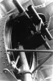
Aft Fuselage |
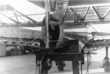
Aft Fuselage |
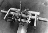
Pitch Trim Mechanism |
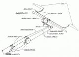
Pitch Trim Mechanism |
Landing Gear
Each main gear unit was composed of four major parts: the wheel/brake assembly, upper wheel fork/shock strut assembly, lower wheel fork assembly, and the landing gear/wire Vee strut. Goodyear 18x8/4 ply low pressure tires (12-1/2 psi inflation pressure) were mounted to Goodyear hubs that incorporated internal disc type brakes. The hubs revolved on two tapered roller bearings that were packed in grease and mounted to an axle tube that in turn was inserted into the bronze bearings of the upper and lower wheel forks. A retaining nut and thru-bolt held the axle in place. The shock absorber strut was an oleo strut which connected the lower wheel fork to the upper end of the landing gear strut. An adjustment at the lower end of the Vee strut provided for wheel alignment.
Each main wheel was equipped with an internal disc brake. The brakes were actuated by cables which originate at heel pedals. The brake linkage was such that a foot pedal force of 75 lbs locked the wheel under landing and taxiing conditions. For operation from muddy fields an auxiliary spring was utilized to assure that the brakes release fully.
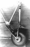
Main Gear Assy |
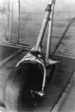
Main Gear Assy |
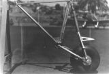
Main Gear Assy |
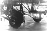
Main Gear Instl |
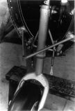
A good year 8 inch streamline tire and hub (29 psi inflation pressure) was utilized as a tail wheel. Early models had trombone type strut. Later an oleo shock strut with steerable tail wheel was offered as an option and the option in turn became standard equipment. A horn mounted to the struts cap connected the wheel to the rudder horn via steering springs.
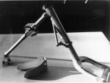
Tailwheel Weldment |
Aft Fuselage |
Aft Fuselage |
Instruments
The factory standard equipment included a compass, an oil pressure and temperature gauge, an altimeter, a tachometer and an air speed indicator.
Powerplant
The Ryan ST series aircraft were powered as follows:
Model         Engine             Power
ST            Menasco B-4        95 hp @ 1975 rpm
ST-A          Menasco C-4        125 hp @ 2175 rpm
ST-A Special  Menasco C-4S       150 hp @ 2275 rpm
The STM was equipped with either the C-4 or the C-4S. The STM's delivered to China (sometimes known as the STC-4) were equipped with Menasco C-4S2 engines (165 hp).
The engine controls consisted of a throttle/mixture quadrant mounted on the left cockpit wall, a primer lever and a magneto switch.
Fuel System
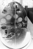
The fuel tank was a 24 gallon welded aluminium tank that was strapped to aluminium angles inside the fuselage and aft of the firewall. The tank incorporated internal baffles and had a float type gauge which actuated a thin rod that stuck up out of the fuselage. At full fuel the rod was noticably extended while at empty it was almost completly inside the tank. Two pipes led from the bottom of the tank: a main fuel line and a reserve line. The main line utilized a standpipe to provide 30 minutes normal fuel for the reserve line. Both outlets incorporated finger strainers with #10 mesh.
The standard Menasco C-4 installation (used in the ST-A) consisted of 3/8 inch copper lines which led from the tank outlets to a fuel cock that was located on the #1 bulkhead. A torque tube led from the fuel cock to a handle in the pilots cockpit and allowed for switching between off, reserve and main. A 3/8 inch copper line connected the fuel cock to a gasoline strainer that was clamped to the engine mount. From there another 3/8 inch copper line led to a wobble pump, onward to the engine driven pump and thence into the carburetor. A 3/8 inch copper bypass line was routed from the fuel pump outlet back to the wobble pump outlet. A 1/4 inch copper line led from the wobble pump outlet to a fuel pressure gauge located in the pilots cockpit. All fuel lines incorporated flexible hose connections to absorb vibration and prevent fatigue failures. The wobble pump was used to provide fuel to the carburetor in the event the engine driven pump failed.
The Menasco C-4S Installation (as used in the ST-A special and STM) differed in that it utilized 1/2 inch copper line in place of 3/8 inch copper line. The C4S installation also omited the wobble pump as the engine's favorable carburetor location allowed for the gravity feed of fuel through the complete system.
Fuel Tank |

Fuel System Schematic |
Oil System
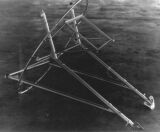
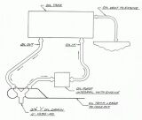
The oil tank was constructed of welded aluminium sheet and mounted forward of the firewall and above the engine. The tank was held in place by steel straps that terminated in lugs which were bolted to Lord rubber mountings which in turn fastened onto the engine mount. A 3/4 inch 3SO aluminium tube led from the tank to the oil pump with a similar return line leading back to the tank. A 1/2 inch 3SO vent line led from the tank's upper right side to the engine's crankcase. Flexible hose connections were used and all lines had a minimum wall thickness of .042.
Engine Mount Note: Oil Tank Attachment Provisions |
Oil System Schematic |
Seaplane Variant
The Ryan STM-S2 were delivered with Edo Model 1965 floats. They also featured a larger front spar in the stub wing and used a single pair of streamline wires between the two floats instead of two counter wires. Water rudders were installed which were retracted and steered from the cockpit. The interior of these airplanes was treated with zinc chromate.
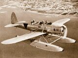
Ryan STM-S2 Photo: Northrop Grumman |
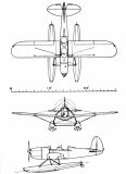
Ryan STM-S2 Source: Northrop Grumman |