This webpage is not "official" data and should not be mistaken for nor used as approved data. This document should not be used for the operation or maintenance of a real aircraft.
- Fuselage Construction
- Wing Construction
- Ailerons and Flaps
- Empennage Construction
- Elevator and Rudder Control
- Elevator Tab Control
- Landing Gear
- Instruments
- Powerplant
- Fuel System
- Oil System
- Seaplane Variant
Fuselage
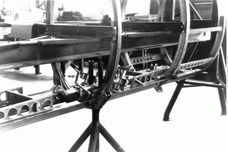
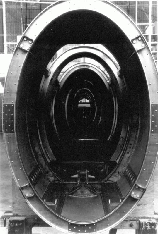
The fuselage structure consisted of eight elliptical bulkheads covered with 6 pieces of 24ST aluminium sheet. The bulkheads were numbered 1 to 8 starting at the firewall which is Bulkhead #1. Bulkhead #2 and the lower portion of #3 were made from SAE 4130X steel and heat treated to 180,000 psi. The remaining bulkheads were made from 24ST aluminum sheet which is formed into elliptical hat sections.
Three longitudinal skins covered the fuseulage between bulkheads #4 and #8. The joints between these skins were at the top of the fuselage and on each side below the center. The three forward fuselage skins were wrapped around the bulkheads with the joints at the top of the fuselage. Longitudinal "hat section" members were used to carry loads around the cockpit cutouts. These stringers were mounted on the inside of ST-A, PT-16 and early STM models. The stringers were mounted on the outside of PT-20, NR-1 and late STM models.
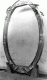
Bulkhead No.2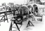
Fuselage Assy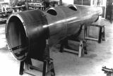
Fuselage Assy
Fuselage Assy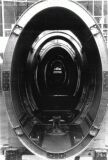
Fuselage Assy
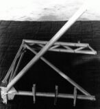
Wings
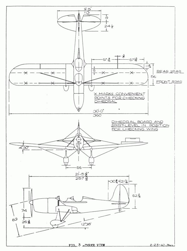
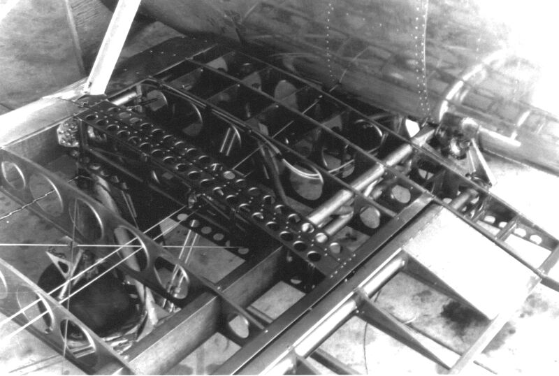
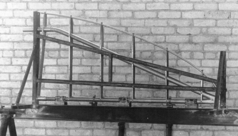
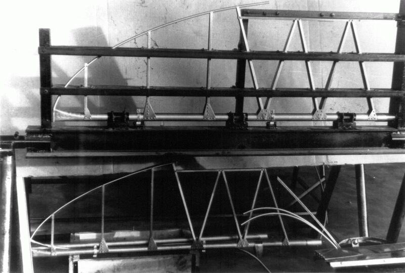
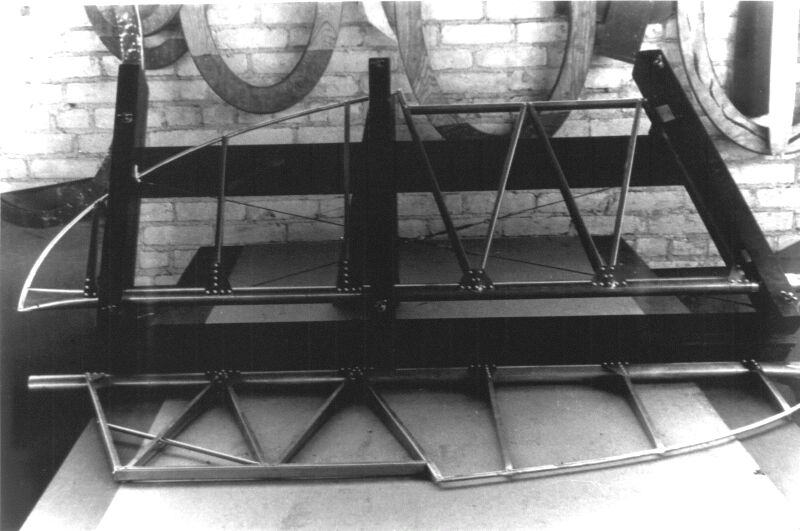
The Ryan ST wings had an NACA 2412 airfoil and were externally braced with streamline tie rods. The flying wires were double wires and the landing wires were single wires. The wings themselves consisted of a stub wing and an outer panel. The stub wings were constructed primarily of 4130X steel tube which is heat treated to 180,000 psi. The outer panels had solid spruce "plank" spars. Renforceing blocks were glued onto the spars in the vicinity of the flying and landing wire attachments. Each of the outer panels had 5 drag bays. Single round tie rods and double SAE 1025 steel tube compression struts make up the drag bays. The tubes of the compression struts were spread as rfar apart as the airfoil permits thereby reducing any tendancy for the spars to roll.
The wing ribs were stamped from 24ST .0201 thick clad sheet with flanged lightning holes and spar cutouts. Each rib was fastened to the spar with one riveted steel bolt (a regular AN bolt and nut with the end flatened to prevent the nut from backing out) through the spar's neutral axis and two wood screws. The wing's leading edge was covered with .0159 24ST aluminium sheet. The leading edge skin was attached to the ribs with rivets and sheet metal screws.
Wing Root Weldment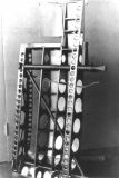
Wing Root Detail
Wing Root Detail
Wing Root Detail
Wing Assy
Outer Wing Detail
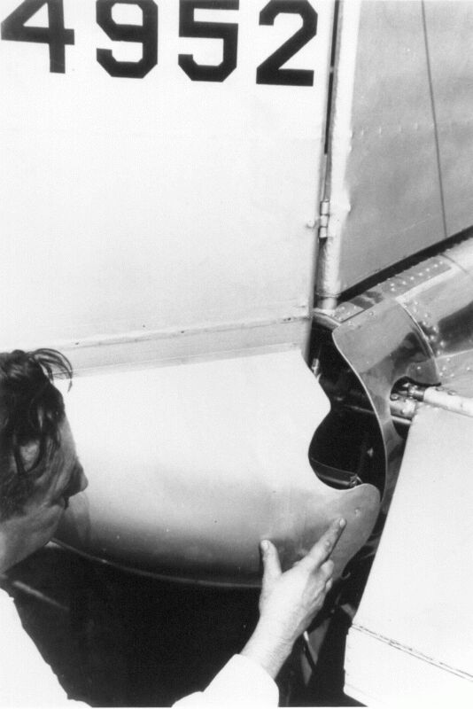
Wing Root Fillet
Ailerons and Flaps
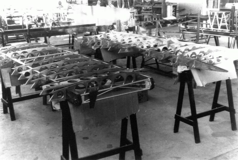
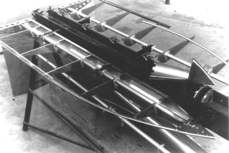
The ailerons and flaps had an SAE 4130X steel spar with welded lugs to which 24ST aluminium alloy ribs were riveted. The leading edge was wrapped with a .015 alloy sheet and the entire surface was in turn covered with fabric. The ailerons were partially balanced as the hinges are located behind the leading edge.
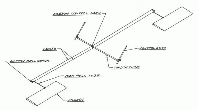
The ailerons were controled with 1/8 inch extra flexible cable which connected the stick to a bellcrank that actuated a push rod that in turn moved the surface. The bellcrank was attached to a bracket that was weleded onto a compression strut.
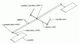
Aileron Schematic
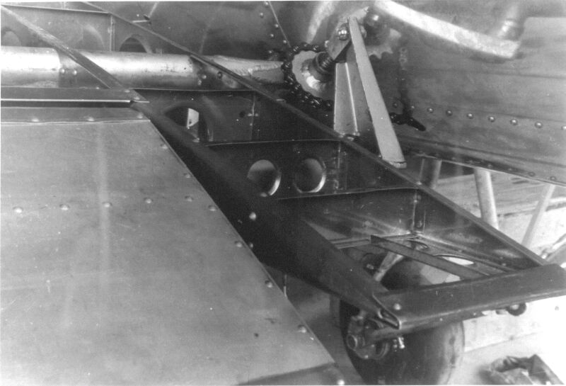
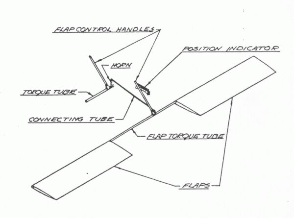
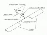
AileronsEach flap was carried on three aluminium brackets which extended from the aft spar at the drag fittings. Inside these brackets were bronze bushings which were insulated from the aluminium. A steel torque tube extended from inboard side of the flap spars and connected to a universal joint which linked the two sides. The flap operating handle found on later aircraft was mounted to the right hand flaps torque tube.
On the prototype (s/n 101) through s/n 119 the flaps extended all the way to the fuselage, after that they terminated at the stub wing. The early flap installation (s/n 101-117) was actuated by a hand crank located in the lower right corner of the pilots cockpit (near the pilot's ankle.) The crank was connected to the flap torque tube with an ordinary 1/8 inch pitch bicycle chain. To fully extend the flaps 32 rotations of the handcrank were required. Unfortunatly to reach the crank the pilot had to lean forward and reach to the floor, visibility outside the cockpit was limited during this lengthy process. As a result the flap mechanism was replaced with a simple handle starting with s/n 118. The later flap handle featured a trigger on the top of the handle which allowed the flap to locked at four seperate positions between 0 and 45 degrees.
Empennage
The empennage was constructed of 17ST aluminum tube with stamped 24ST aluminium ribs riveted to the tubes. The surfaces were covered with fabric and externally braced with streamline tie rods.

Horizontal Stabilizer
Elevator
Elevator
Tailcone